Motor Control Systems
Motor Drive Package
All-in-one platform for motor control learning,
inverter testing, and real-time development.

What is the Motor Drive Package?

Motor Drive Package The Motor Drive Package is a integrated platform that includes the control system (controller/integrated development environment/motor software control*) and the drive circuits (inverter/MG set or real-time simulator) required for motor control development, along with all required documentation and manuals.
*For permanent magnet synchronous motors
Customers only need to provide a single-phase 100 VAC power source. The system is ready for operation immediately after delivery, without the hassle of determining specification requirements, system design, or control design.
Product summary
The control systems included in this package are the PE-Expert4 controller and the integrated development environment PE-ViewX, with extensive deployment across a wide range of power electronics R&D applications and development applications in the power electronics industry. Equipped with a high-performance DSP, these systems can be used in research and development applications requiring advanced control design after basic motor control has been mastered.
The drive circuits used with this package include the PE-Inverter/motor (MG-set), an inverter configuration capable of providing the user with a hands-on understanding of motor control behavior, for the physical version, and the HILS version, which utilizes the Typhoon HIL real-time simulator.
The physical version comes with a mini inverter with current and voltage sensors, along with a motor equipped with an encoder, as well as all necessary power supplies and wiring. The motor can be driven with only simple wiring work. It also comes with a transparent cover for safe operation monitoring.
The HILS version allows users to develop control software without risk of hardware damage, even if you are inexperienced with motor control. HILS is very compact and safe, making it easy to develop motor control software right on your office desk.
Easy to Use Even for Beginners
This package includes motor control software and manuals, allowing you to operate the motor and understand the behavior of control programs, even if you have no prior experience with motor control. Once you have read the manual and understand the control program included, the program can be used to deepen your understanding of motor control, making this system ideal for mastering motor control.

For Engineers Learning Motor Control
- Operate a physical motor using motor control software, giving users a hands-on understanding of motor control behavior.
- Measure motor voltage, current, and phase signals in real-time, giving you a better understanding of control algorithms.
Those looking to use the system for development
- Control the carrier frequency, control gain, and other parameters in the motor control software. Observe how changes affect the motor's behavior and responsiveness in real-time.
- Accelerate development by modifying and extending the control software based on the motor control software.
Example System Configurations


Click image to enlarge
Motor Control Software Overview
Motor Control Software
The motor drive package comes with motor control software that has been widely adopted in motor control R&D.
The motor control software is optimized for the motor and inverter included in the motor drive package.
After purchase, the software is tuned for use with your motor and inverter.
*Note that warranty coverage is limited to the motor drive package provided by Myway Plus.
Fundamental Control Method: Vector Control
- The three-phase motor current is converted into a rotary coordinate system (dq-axis) to control the dq-axis current.
- The outer control loop performs speed control processing, which can be executed at relatively low speeds. This is performed in 2 ms cycles.
- PI control is performed between the speed command value and the speed at the time, and the current command value is updated.
- The inner current-control loop performs current control required for high-speed processing. This is performed in 100 us cycles.
- PI control is performed between the current command value and the speed updated for the outer control loop, and the gate signal command value is updated.

Click image to enlarge

Click image to enlarge
Available Control Methods
In addition to basic vector control, the option is available to add software for a broad range of established control methods. Control methods that can be added include the following.
120-degree Square Wave Drive
120-degree square wave drive is a motor control technique that involves switching the direction of current in 60-degree intervals.
The diagram shows the directions of current and magnetic flux during the intervals of 30 to 90 degrees, and 90 to 150 degrees.
The blue arrows represent the current, while the red arrows indicate the resultant magnetic flux.
The motor rotates according to the generated magnetic field direction.
The gate signals for each phase are output with a 120-degree phase difference, synchronized with the 120-degree square wave commutation period. Control in each phase is as described below. U-phase: 30 to 150° V-phase: 150 to 270° W-phase: 90 to 210° The upper arm in each phase outputs the PWM signal, while the lower arm outputs the all ON signal. This is used to operate the motor in the direction of the resultant magnetic flux.
Specialized Cabinet Specifications

Click image to enlarge
Operating Environment

Click image to enlarge

Click image to enlarge
Sensorless Vector Control
Sensorless vector control is a method of motor control that does not involve the use of a rotational sensor.
While there are several methods for achieving this, this package uses a control method based on current estimation errors.
As sensorless vector control does not involve the use of a rotational sensor, it is not possible to accurately detect the motor's magnetic flux component (d-axis) and torque component (q-axis). In the current estimation error method used in this package, the γδ-axis is defined based on estimations of the motor's voltage equations, instead of the dq-axis.
This estimation requires prior knowledge of parameters such as the inductance values of the motor's armature windings, and the resistance values of the armature. The estimated current is calculated based on these motor-specific parameters during motor operation. The error between the estimated current and the actual current values obtained from the inverter's current sensor is used for feedback control. In other words, feedback control is applied to align the dq-axis with the estimated γδ-axis.
Key Functions of PE-ViewX

Click image to enlarge
Configure Command Values and Tune Control Gains in PE-ViewX
Use the Inspector window in PE-ViewX to monitor and modify global variables while the program is running.
Global variables set for the motor control software are described in the manual, including descriptions of what each variable means.
Use the Inspector window to adjust the speed command value, and the speed PI gain, current PI gain, carrier frequency and other settings while the control program is running. This feature provides an easy way to set command values and adjust control gains.

Click image to enlarge
Monitor Waveforms in PE-ViewX
The WAVE window in PE-ViewX allows you to monitor global variable values while the program is running, and display real-time waveforms in an oscilloscope-style interface.
This provides an easy way to check waveforms for each variable after setting command values or adjusting the control gain in the Inspector window.
Additionally, the WAVE window can display up to four screens, allowing you to assign current waveforms, dq-axis current commands, modulation rates, angles, and more from the top down.
Using these four screens, you can observe the speed tracking performance and current control behavior during speed changes, as well as cross-check current waveforms during error occurrences.
MATLAB/Simulink® Integrated Motor Control Development

The vector control feature provided with the motor control software for the motor drive package includes a MATLAB/Simulink-integrated package.
- MATLAB/Simulink model (for current control part only)
- Platform software for executing generated control C code

Click image to enlarge
MATLAB/Simulink integration enables control design and tuning in the following four easy steps.
- Design the control model in Simulink
- Automatically generate the control C code with Embedded Coder
- Build and download the control C code in PE-ViewX
- Debug and tune parameters in PE-ViewX
This significantly reduces the time required for program development, enabling rapid evaluation of multiple control strategies.
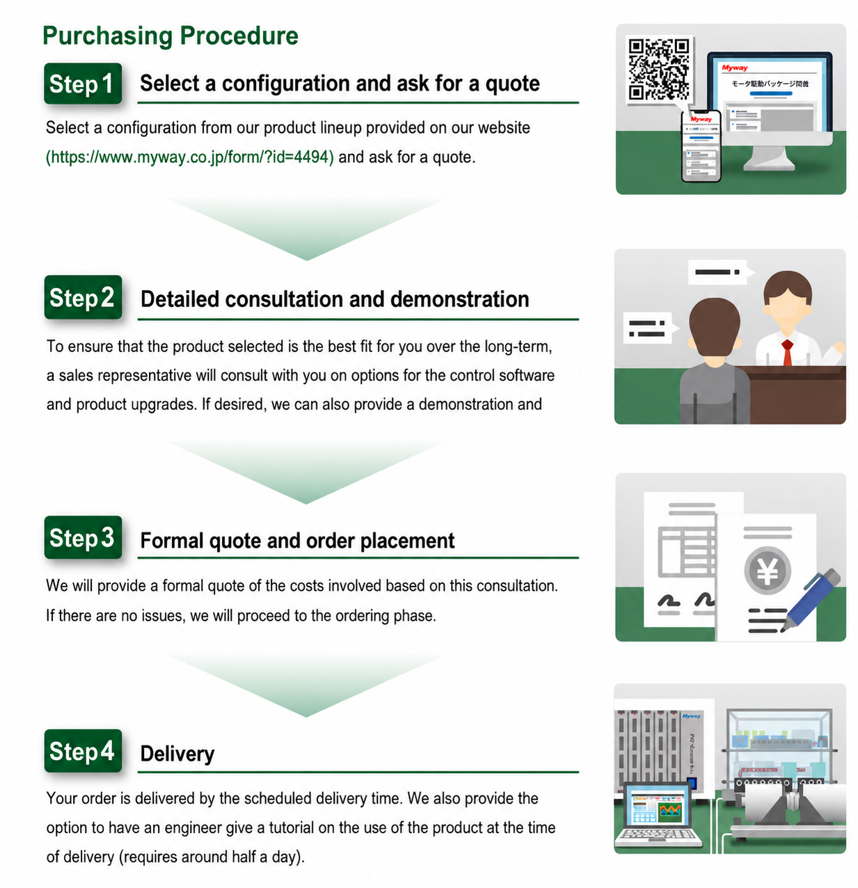
PURCHASING PROCEDURE
From Evaluation to Deployment
Select a configuration and ask for a quote, receive detailed consultation and demonstration, proceed with formal quotation and ordering, and receive delivery with engineering support.
Ready to explore Motor Drive Package?
Download the product brochure or contact our engineering team for detailed technical information and evaluation support.